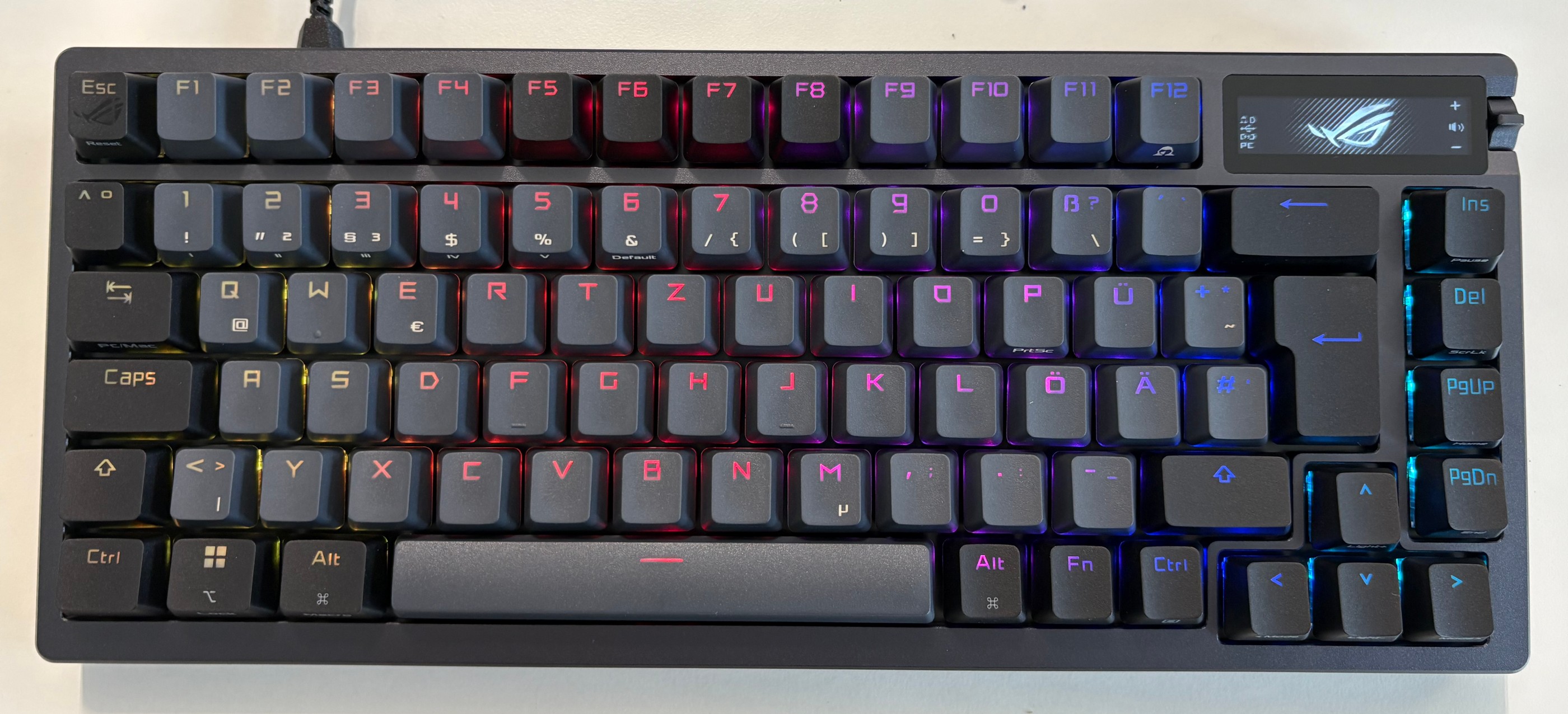
The Asus ROG Azoth is a high-end gaming keyboard built to be a bit smarter than normal keyboards. Solid tactile switches, fully customizable RGB lighting, and a crisp built-in OLED display put it a step above the usual. That little screen isn’t just for looks: It can show system stats, adjust lighting profiles, tweak volume, and act as a quick access hub for keyboard settings without touching your OS.
 Asus ROG Azoth
What makes the Azoth really interesting isn’t just the hardware, though – it’s what you can do with it. The keyboard’s onboard microcontroller and flexible firmware open the door to deeper exploration. In this blog post, we detail a hardware hacking project where we threw out the stock code, got under the hood of the Azoth’s software stack, and set the stage to run custom code directly on the keyboard itself. The ultimate stunt: flashing a minimalist version of Doom to play on the Azoth alone – no extra hardware, just pure embedded mischief.
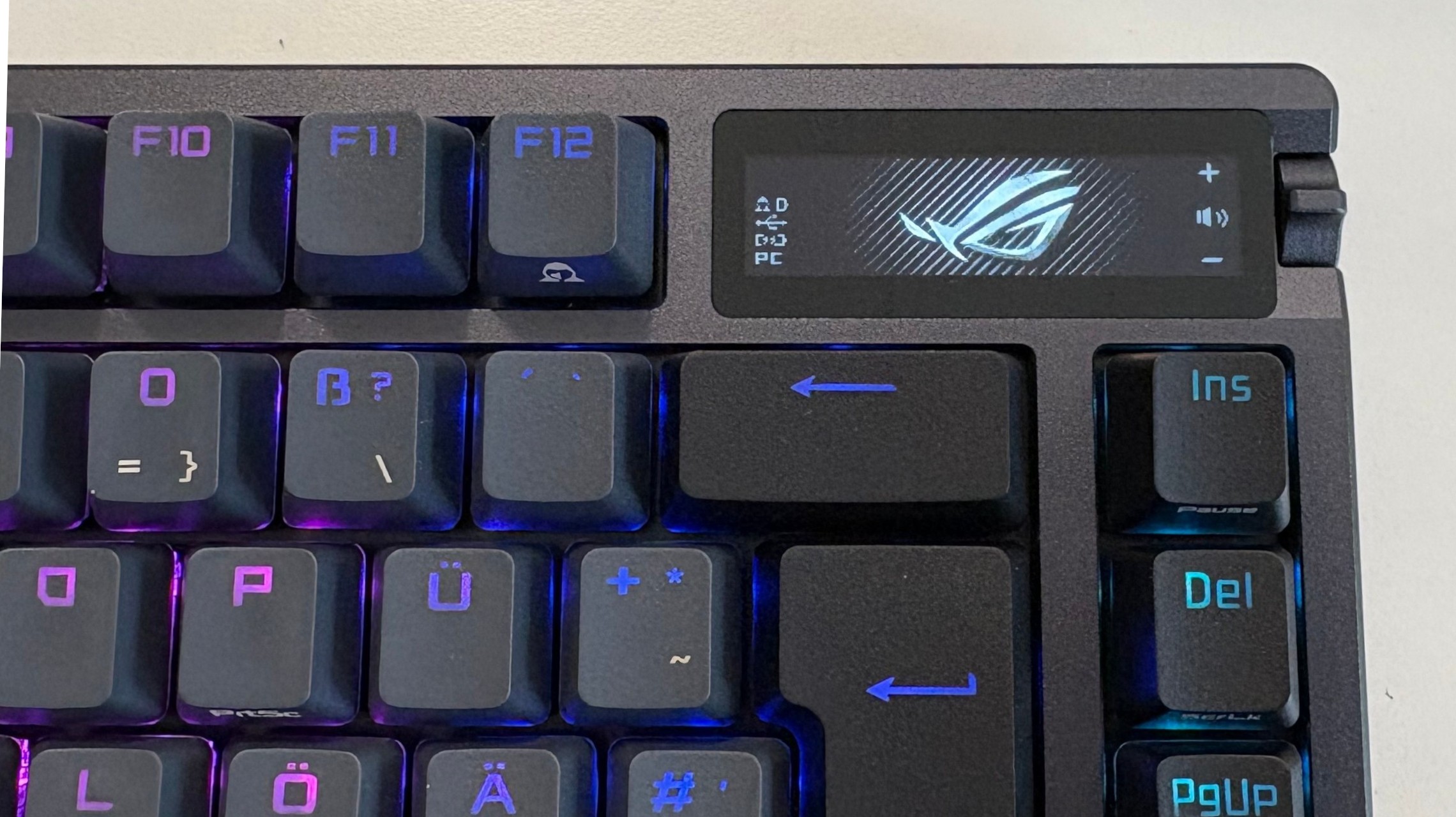 ROG Azoth display
Is your companion doomed?
The ROG Azoth is powerful, and clearly designed to blur the line between a passive input device and an active system companion. That same “smart” design is exactly what makes the Azoth interesting from a security and research perspective. A keyboard with its own display, storage, firmware update path, and microcontroller is no longer just a dumb HID device. It’s a computer on your desk that happens to inject keystrokes. From a hardware security standpoint, that raises real questions: How locked-down is the firmware? What trust assumptions does the host OS make about the device? And how much control does the user actually have over the code running inside it?
Hacking a device like this isn’t just a gimmick or a flex. It’s a practical way to audit the security boundaries of modern peripherals. If custom code can be injected, what prevents malicious firmware from doing the same? If the display and input logic are programmable, could the keyboard lie to the user, exfiltrate data, or act as a covert attack platform? These aren’t theoretical problems – they’re exactly the kinds of attack surfaces that get ignored because “it’s just a keyboard.”
That’s why this project aims higher than blinking LEDs or custom animations. By reversing the Azoth’s software stack and targeting its microcontroller directly, we explore how resilient the platform really is. The stunt goal – running a stripped-down version of Doom entirely on the keyboard – isn’t about gaming on an OLED strip. It’s a proof of capability. If you can play Doom on it, you can run arbitrary logic on it. And once you reach that point, the conversation stops being about fun hacks and starts being about trust, firmware security, and how much power we’re quietly handing to “smart” peripherals.
Enumerating the attack surface
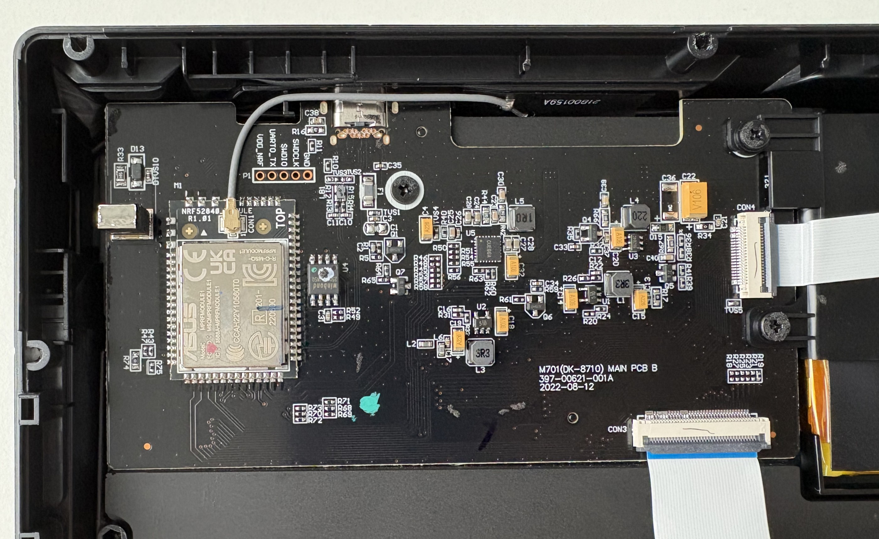
With the case removed, the main PCB was subjected to a detailed component-level analysis. The most interesting part is a custom ASUS-developed module based on the Nordic nRF52840. This SoC is well-known in the embedded world: ARM Cortex-M4, plenty of flash and RAM, USB support, and native SPI/I2C/UART peripherals. In other words, more than powerful enough to run complex firmware – and definitely powerful enough to run things the vendor never intended. A picture of the motherboard is shown below.
 ROG Azoth motherboard
During the PCB inspection, a small pin header stood out, labeled VDD_NRF, UART_TX, SWDIO, SWCLK, GND. SWD (Serial Wire Debug) is ARM’s standard two-wire debugging and programming interface for Cortex-M microcontrollers. Using just SWDIO (data) and SWCLK (clock), a debugger can halt the CPU, read and write memory, flash firmware, and single-step through code – if no firmware protection is enabled. It’s how developers bring firmware onto the chip during manufacturing and how they debug it during development.
From a security perspective, an exposed SWD header is gold. If SWD is left enabled and not properly locked down, it can provide full, low-level access to the microcontroller – below the operating system, below any application logic, and below any software-based protections. Firmware readout, live memory inspection, and arbitrary code injection all become possible with minimal hardware.
The OLED display resides on its own small PCB, connected to the main board via a flat cable. The panel itself appears to be a monochrome OLED of unknown exact model. Although there is no public documentation from ASUS, the PCB markings and trace layout make it obvious that this display is driven via the SPI protocol.
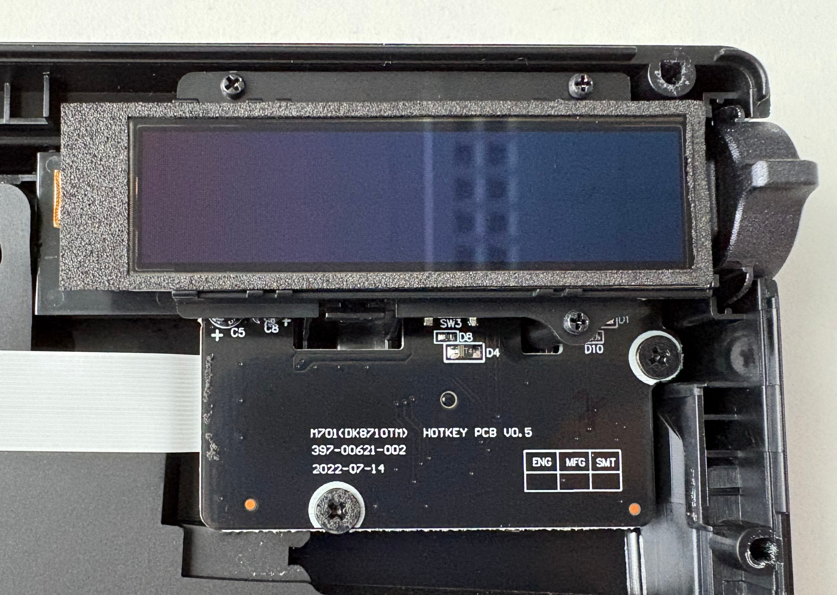 Detailed view of the ROl Azoth OLED display
SPI (Serial Peripheral Interface) is a simple, synchronous communication protocol commonly used between microcontrollers and peripherals like displays, sensors, and flash chips. It uses a shared clock line and separate data lines for sending and receiving data, plus a chip-select signal to choose the active device. There’s no encryption, no authentication, and no inherent access control – if you can talk on the bus, you can control the device.
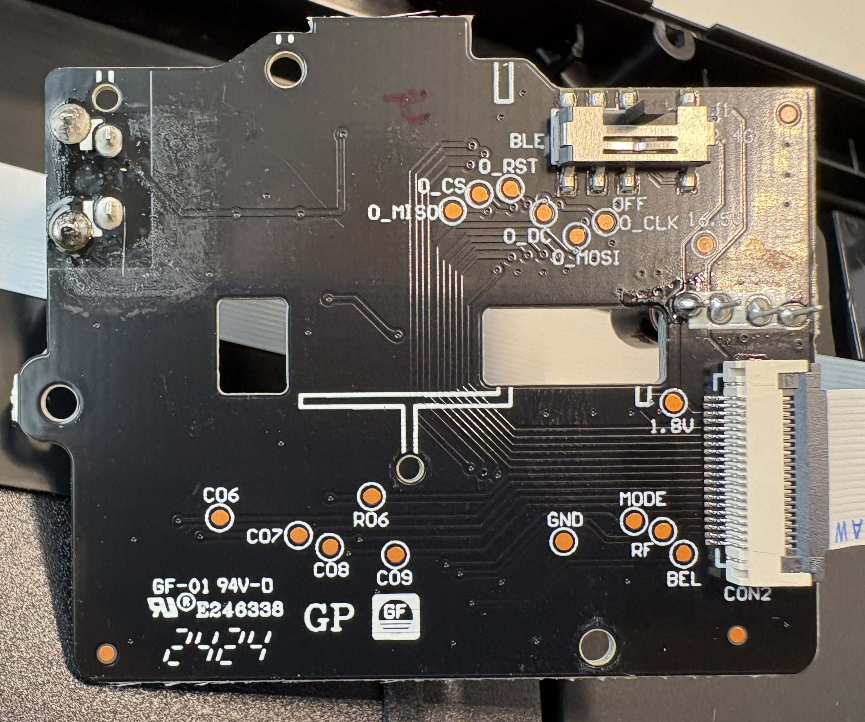 OLED display PCB markings
By this point, the boundaries were clear. A powerful microcontroller running vendor firmware, a display controlled over SPI, and a firmware update path to tie it all together. That combination defines the core surface to probe: firmware integrity, debug access, and peripheral control.
Gaining access to the keyboard’s firmware
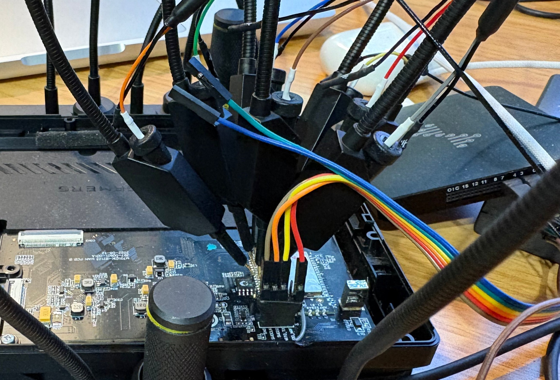
A smart keyboard might have signed firmware, update checks, and polished software – but none of that matters if the debug interface is still accessible. With the SWD header identified, a SEGGER J-Link was connected to the SWDIO, SWCLK, VDD, and GND pins, and the nRF52840 immediately responded. No glitching, no tricks – just a clean debug connection.
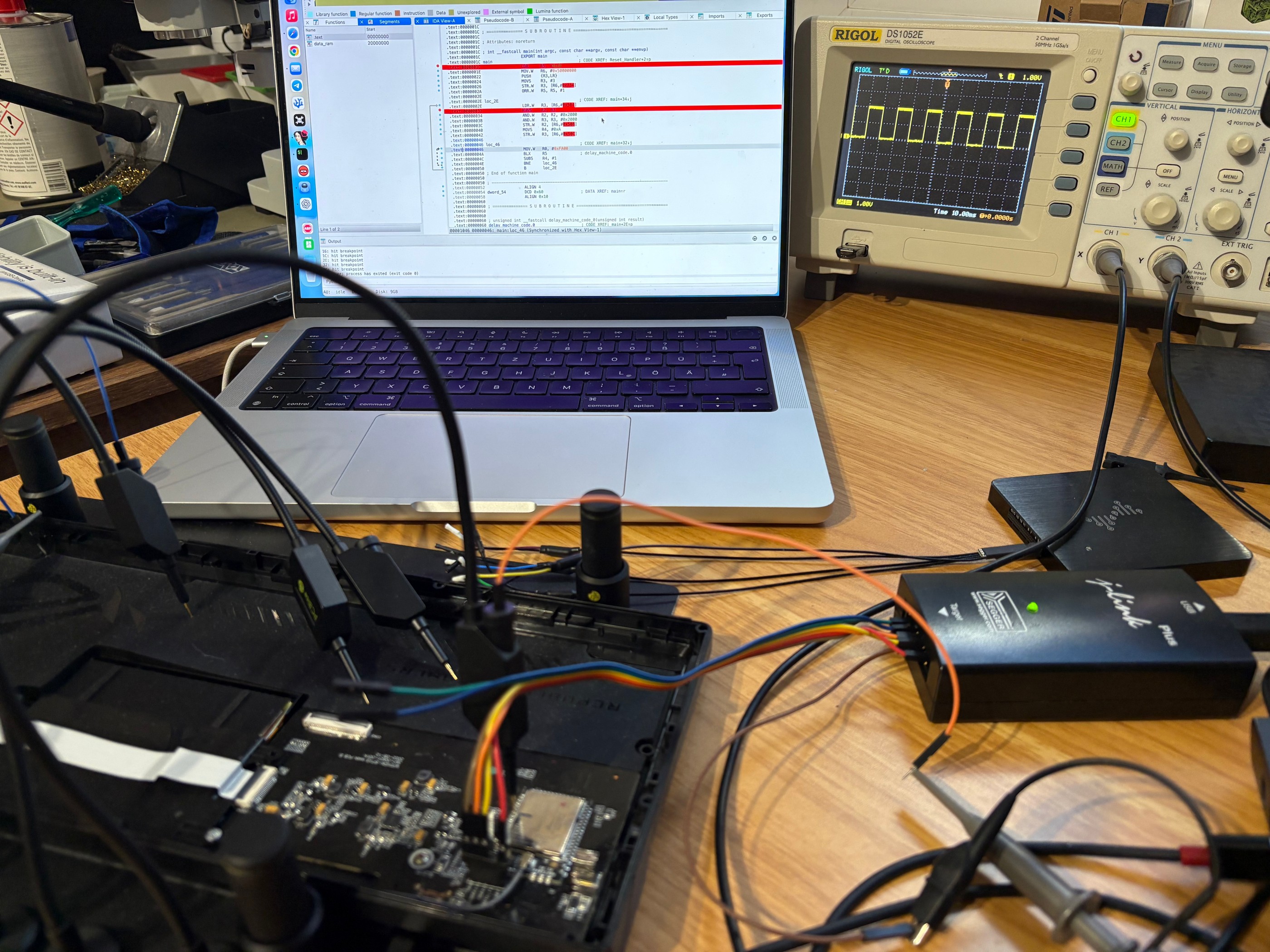 Programming setup
The first critical finding came right away: APProtect was not enabled. That means the entire flash contents could be read out without restrictions. The full factory firmware was dumped and archived. This might not seem like a big issue, but it’s a major security issue – and a major convenience for research. Having a fresh firmware backup is essential if you want to experiment freely and still be able to restore the device to a factory-like state afterward.
An attempt was then made to reverse-engineer the dumped firmware. In theory, this would allow us to understand the full software stack and modify behavior directly. In practice, it was a dead end. The firmware is a large, bare-metal application with no symbols, no debug strings, and heavy use of vendor libraries. Static analysis quickly turns into guesswork, and dynamic analysis without source-level insight is slow and fragile. This is a common problem in embedded research: Having the firmware doesn’t mean it’s realistically reversible.
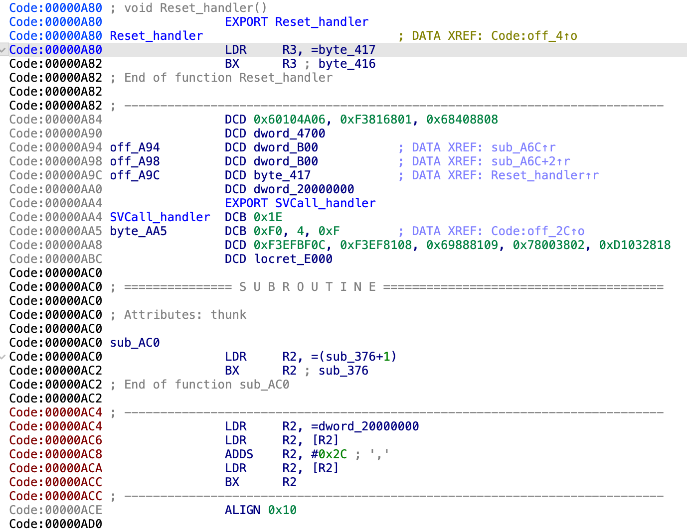 Reverse-engineering the reset handler
Instead of fighting the entire codebase, the focus shifted to something more contained and more useful: the display path. If we could independently drive the OLED, we could replace the UI layer entirely. That meant figuring out how the nRF52840 communicates with the display – which SPI mode is used, which commands initialize the panel, and how pixel data is transferred.
 Signal capturing
Unlike many MCUs, the nRF52 family uses flexible GPIO mapping. SPI signals aren’t tied to fixed pins – they’re assigned in firmware. As a result, there was no shortcut from the datasheet. The PCB itself had to be reverse-engineered to trace the display connector back to specific GPIO pins on the nRF52840.
Understanding the display communication
To see what the firmware actually does, a logic analyzer was hooked up to the lines going from the nRF52840 to the OLED display. Captures were taken right after reset, while the stock firmware initialized the keyboard. This gives a clean view of the display init sequence.
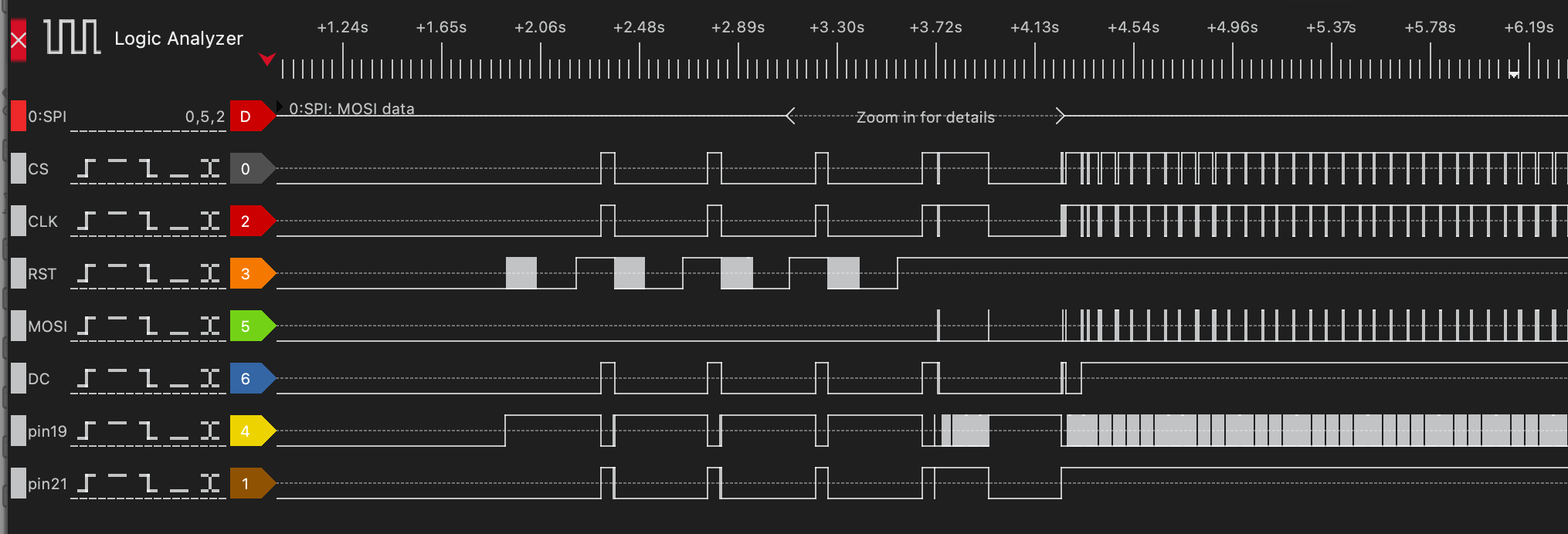 SPI logic trace
The core SPI signals were easy to identify. MOSI (Master Out, Slave In) carries data from the nRF to the display. CLK is the clock that defines when bits are sampled. CS (Chip Select) marks when the display is actively addressed. DC (Data/Command) switches the meaning of the bytes on MOSI – low for display commands, high for pixel data.
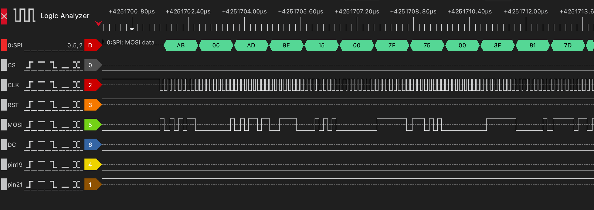 Commands to initialize the display
The function that initializes the display and was finally added to the custom firmware is shown below.
1
2
3
4
5
6
7
8
9
10
11
12
13
14
15
16
17
18
19
20
21
22
23
static void oled_init(void) {
    oled_reset();

    uint8_t cmd[] = {
        0xAB, 0x00,   // Enable internal VDD regulator / unlock OLED command (0xAB = Unlock, 0x00 = enable)
        0xAD, 0x9E,   // Set master configuration (0xAD = Master config, 0x9E = external VDD + internal reference)
        0x15, 0x00, 0x7F, // Set Column Address: start=0x00, end=0x7F (128 bytes = 256 pixels)
        0x75, 0x00, 0x3F, // Set Row Address: start=0x00, end=0x3F (0–63 rows)
        0x81, 0x7D,   // Set contrast / current (0x81 = contrast, 0x7D = value)
        0xA0, 0x51,   // Set Re-map / Segment configuration: horizontal flip (bit A0/A1) -> if other orientation is chosen, high and low nibbles in oled_draw_char must be swapped
        0xA1, 0x00,   // Set Display Start Line (row start address = 0 for top)
        0xA2, 0x00,   // Set Display Offset (vertical scroll offset = 0)
        0xA4,         // Normal display mode (A4 = display RAM content, A5 = ignore RAM)
        0xA8, 0x3F,   // Set Multiplex Ratio: 0x3F = 64MUX (rows 0–63)
        0xB1, 0x11,   // Set Phase Length (driver timing configuration)
        0xB3, 0xF0,   // Set Display Clock Divide Ratio / Oscillator Frequency
        0xB9,         // Use default (dummy, often for precharge period)
        0xBC, 0x04,   // Precharge voltage level
        0xBE, 0x05    // VCOMH voltage level (common voltage)
    };
    const uint8_t length = sizeof(cmd);
    oled_cmd_buff(cmd, length);
}
However, not all lines were that obvious. Activity was visible on the display’s RESET line, but it didn’t behave like a simple one-time reset. Even more confusing were the GPIO pins 19 and 21, both showing transitions that didn’t line up with SPI transfers. At first glance, they looked unrelated or redundant. Digging deeper cleared things up. The display turns out to have a sleep mode that must be explicitly disabled. Driving GPIO pin 21 high brings the panel out of sleep and allows it to respond to SPI commands. Without this signal, the display stays dark, no matter how correct the SPI traffic is.
The power sequencing was the final missing piece. The OLED is not powered continuously; its supply rails are gated. Two additional GPIOs – pin 46 and pin 47 – control the display’s power circuitry. Unless these pins are asserted in the correct order, the panel is effectively unpowered.
Once all of these signals were understood – SPI, reset behavior, sleep control – and after the power was enabled, the display could finally be driven.
Rendering text on the OLED
With full control over the display signals, the next step was making it actually useful. That meant rendering text – not by abusing the vendor firmware, but by driving the OLED directly with custom code.
A small rendering pipeline was implemented from scratch. Bitmap glyphs were defined for each character, and a function called oled_draw_char was developed to convert those glyphs into the exact binary format expected by the display controller. This includes packing pixels into bytes correctly and sending them over SPI with the right command/data framing.
1
2
3
4
5
6
7
8
9
10
11
12
13
14
15
16
17
18
19
20
21
22
23
24
25
26
27
28
29
30
31
32
33
34
35
36
37
38
39
40
41
static void oled_set_cursor(uint8_t col, uint8_t row) {
    // Row: 0..63
    uint8_t cmd1[] = {0x75, row, row};
    const uint8_t length1 = sizeof(cmd1);
    oled_cmd_buff(cmd1, length1);

    // Column: 0..127 (each byte = 2 pixels)
    uint8_t cmd2[] = {0x15, col, 0x7F};
    const uint8_t length2 = sizeof(cmd2);
    oled_cmd_buff(cmd2, length2);
}

static void oled_draw_char(uint16_t x, uint8_t y, char c) {
    if (c < 32 || c > 126) c = '?';
    const uint8_t *glyph = font5x7[c - 32];

    // x_byte = byte address (2 pixels per byte)
    uint8_t x_byte = x >> 1;
    uint8_t shift  = x & 1;  // which nibble (high=0, low=1)

    // iterate each row
    for (uint8_t row = 0; row < 7; row++)
    {
        uint8_t line[3] = {0}; // 5 pixels => max 3 bytes (ceil((5+shift)/2))

        for (uint8_t col = 0; col < 5; col++) {
            if (glyph[col] & (1 << (6 - row))) { // MSB = top pixel
                uint8_t px = col + shift;
                uint8_t idx = px >> 1;

                if (px & 1)
                    line[idx] |= 0x0F; // low nibble
                else
                    line[idx] |= 0xF0; // high nibble
            }
        }

        oled_set_cursor(x_byte, y + row);
        oled_data(line, (shift + 5 + 1) / 2); // number of bytes to send
    }
}
On top of that, a higher-level helper function, oled_draw_string, was added. This function simply iterates over a string, calls oled_draw_char for each character, and advances the cursor position accordingly.
1
2
3
4
5
6
7
static void oled_draw_string(uint16_t x, uint8_t y, const char *str) {
    while (*str) {
        oled_draw_char(x, y, *str++);
        x += 6; // 5 pixels + 1 spacing
        if (x > 255) break; // wrap prevention
    }
}
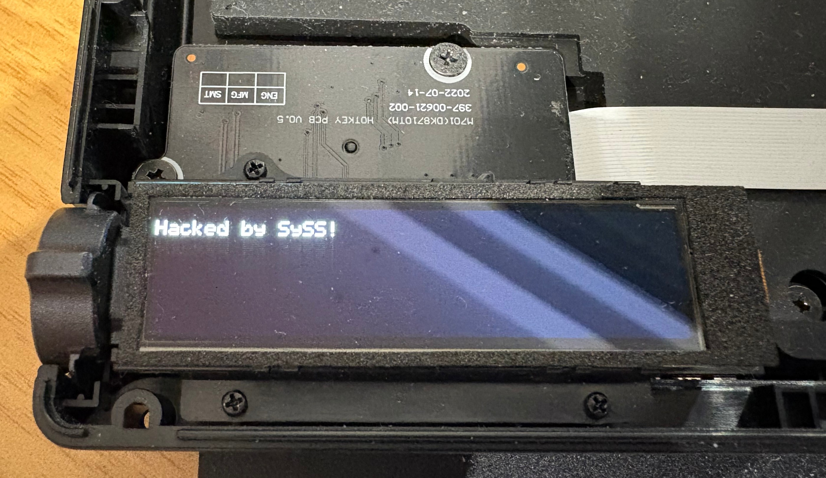
Rendering a custom message then became as simple as calling:
1
oled_draw_string(0, 50, "Hacked by SySS!");
This was the first visible proof that the keyboard was no longer running vendor logic. The OLED wasn’t showing system stats or RGB profiles anymore – it was displaying attacker-controlled content, generated entirely by custom firmware running on the keyboard’s microcontroller.
 Hacked
Verdict
Running a full version of Doom on the ROG Azoth has not yet succeeded. But that was never the real success condition.
What was achieved is far more important from a security and research standpoint. Full access to the keyboard’s microcontroller was obtained, and attacker-controlled code was executed on the device without any restrictions. That alone breaks the assumption that this is a locked-down, trustworthy peripheral.
The hardware itself was mapped and understood. The PCB layout was reverse-engineered far enough to identify critical GPIO functions, power sequencing, and the SPI bus driving the OLED. The display is no longer a black box tied to vendor firmware; it’s a peripheral that can be initialized, configured, and controlled at will.
Finally, custom-rendered text on the OLED proved end-to-end control. The keyboard executes arbitrary code, drives its own display, and presents attacker-defined output – not by glitching or exploiting a runtime bug, but by design choices that left powerful interfaces exposed.
So while Doom remains a stretch goal, the core message is already clear: The ROG Azoth is not just hackable for fun. It’s a reminder that “smart” peripherals are embedded systems with real attack surfaces – and that firmware security matters just as much for keyboards as it does for any other computer on your desk.