Electromagnetic fault injection, or EMFI for short, is a technique used to intentionally introduce faults into electronic systems. By directing high-intensity electromagnetic pulses (EMPs) at a target device, attackers can induce bit flips, crashes or logic errors. This method is particularly useful for evaluating the resilience of embedded systems, cryptographic hardware and microcontrollers. Electromagnetic fault injection is non-invasive, quick, and able to target specific operations, making it a powerful tool for security research and hardware testing.
In this article, a newly discovered fault injection attack on the nRF54L15 microcontroller with the ChipSHOUTER, the Pico Glitcher and the fault injection software libraries findus and emfindus is shown. A public advisory regarding this vulnerability has been issued.
Introduction
An EMFI attack exploits the susceptibility of a microcontroller’s internal logic to high-intensity electromagnetic pulses, which can cause transient faults in computations. By precisely timing an EMFI pulse during a critical operation, such as an arithmetic calculation or cryptographic processing, an attacker can induce bit flips, corrupt register values, or force incorrect branching. This can lead to subtle but exploitable errors, such as incorrect results in authentication checks, bypassed security conditions, or compromised cryptographic outputs. Since EMFI does not require direct electrical contact, it can target even well-protected chips with limited external access, making it a powerful technique for fault-based exploitation.
The Target
The nRF54 is Nordic Semiconductor’s next-generation ultra-low-power wireless System-on-Chip (SoC) series, designed for Bluetooth Low Energy (BLE), Thread, Zigbee, and other radio frequency (RF) applications. It offers higher performance, improved security, a glitch detector, and multiple cores compared to the nRF52 and nRF53 series.
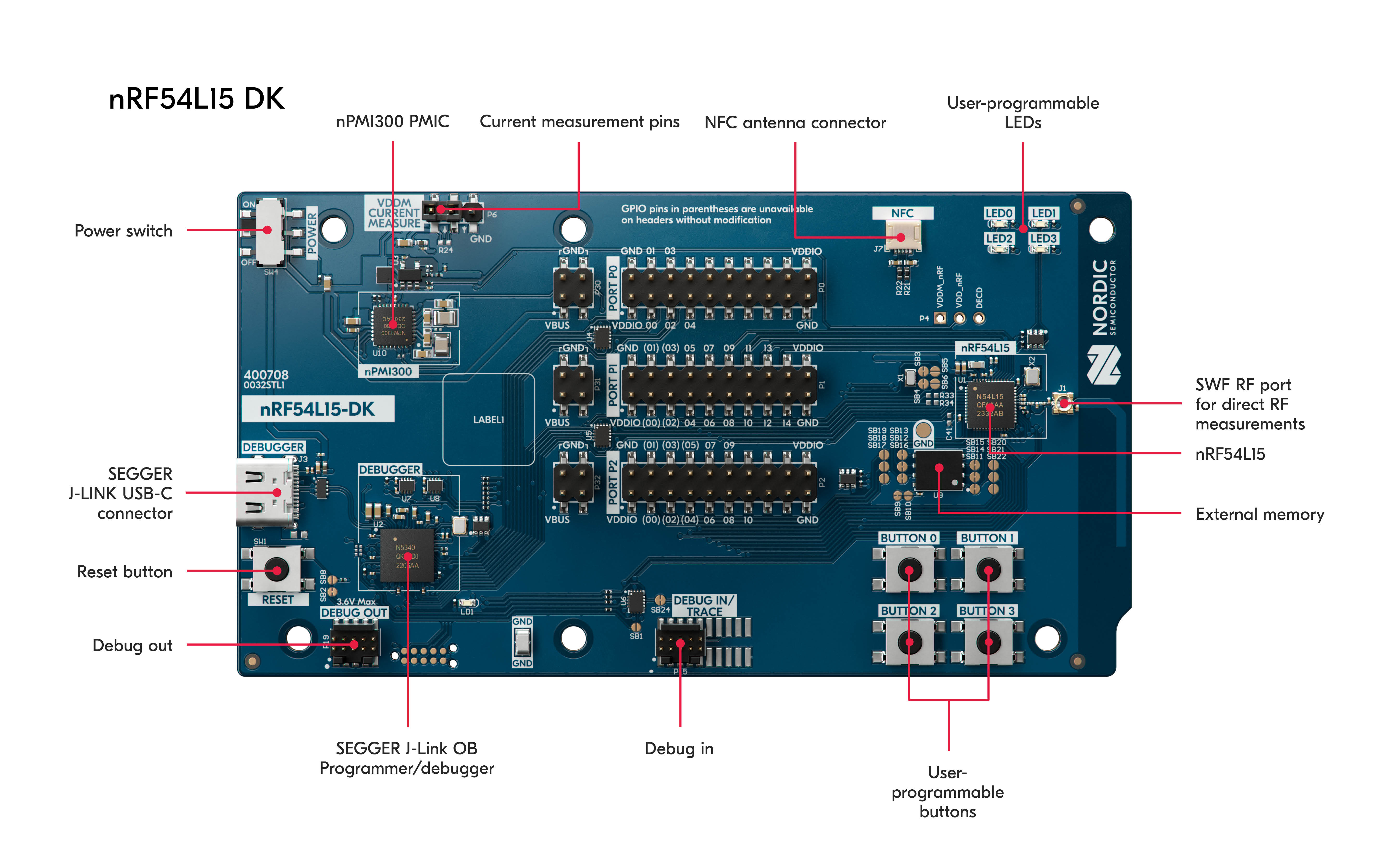 The nRF54L15 target
Security researchers are particularly interested in the configurable glitch detector, as this new technology promises greater resilience against glitching attacks. However, attacks on other microcontrollers (for example Hacking the RP2350, replicated Glitching the Raspberry Pico with a Raspberry Pico) have already shown that a glitch detector can be outsmarted with the right approach. In the case of the attack on the RP2350, voltage glitching was used to cause faults in the microcontroller. In this article, however, the nRF54L15 microcontroller is subjected to electromagnetic fault injection, which is expected to be more effective in evading glitch detection.
For testing purposes, the target was programmed with a simple test program that calculates a checksum over a specified memory range. The trigger signal is generated before the calculation starts. The following is an excerpt of the code that was flashed on the target device.
1
2
3
4
5
6
7
8
9
10
11
12
13
14
15
16
17
18
19
20
21
22
23
24
25
26
27
28
29
30
31
32
33
34

/* configuration and definitions */
...

int main(void) {
    ...

    /* enable glitch detection */
    volatile unsigned int* GLITCHDETConfig = (unsigned int*) 0x5004B5A0;
    *GLITCHDETConfig = 0x00000001;

    /* enable trigger (start glitching) */
    gpio_pin_set_dt(&trigger, 1);

    /* define the data to calculate the checksum on */
    size_t len = 256;
    uint8_t data[len];
    uint32_t crc = 0;
    for (uint8_t rounds = 1; rounds < 3; rounds++){
      /* fill the buffer for CRC calculation */
      for (size_t i = 0; i < len; ++i) {
        data[i] = (uint8_t) ((i*rounds)>>rounds);
      }

      /* calculate checksum over memory area */
      crc = crc + crc24_pgp(data, len);
    }

    /* disable trigger (crc calculation finished) and output calculated crc */
    gpio_pin_set_dt(&trigger, 0);

    /* output crc via UART */
    ...
}
Glitching setup
The setup consists of a ChipSHOUTER to generate EMPs, a CNC table to position the ChipSHOUTER coil precisely above the target device, a Pico Glitcher v2 for trigger generation and control, an adjustable voltage source, and the target board itself (an nRF54L15 development kit). In addition, a logic analyzer and an oscilloscope are used for instrumentation.
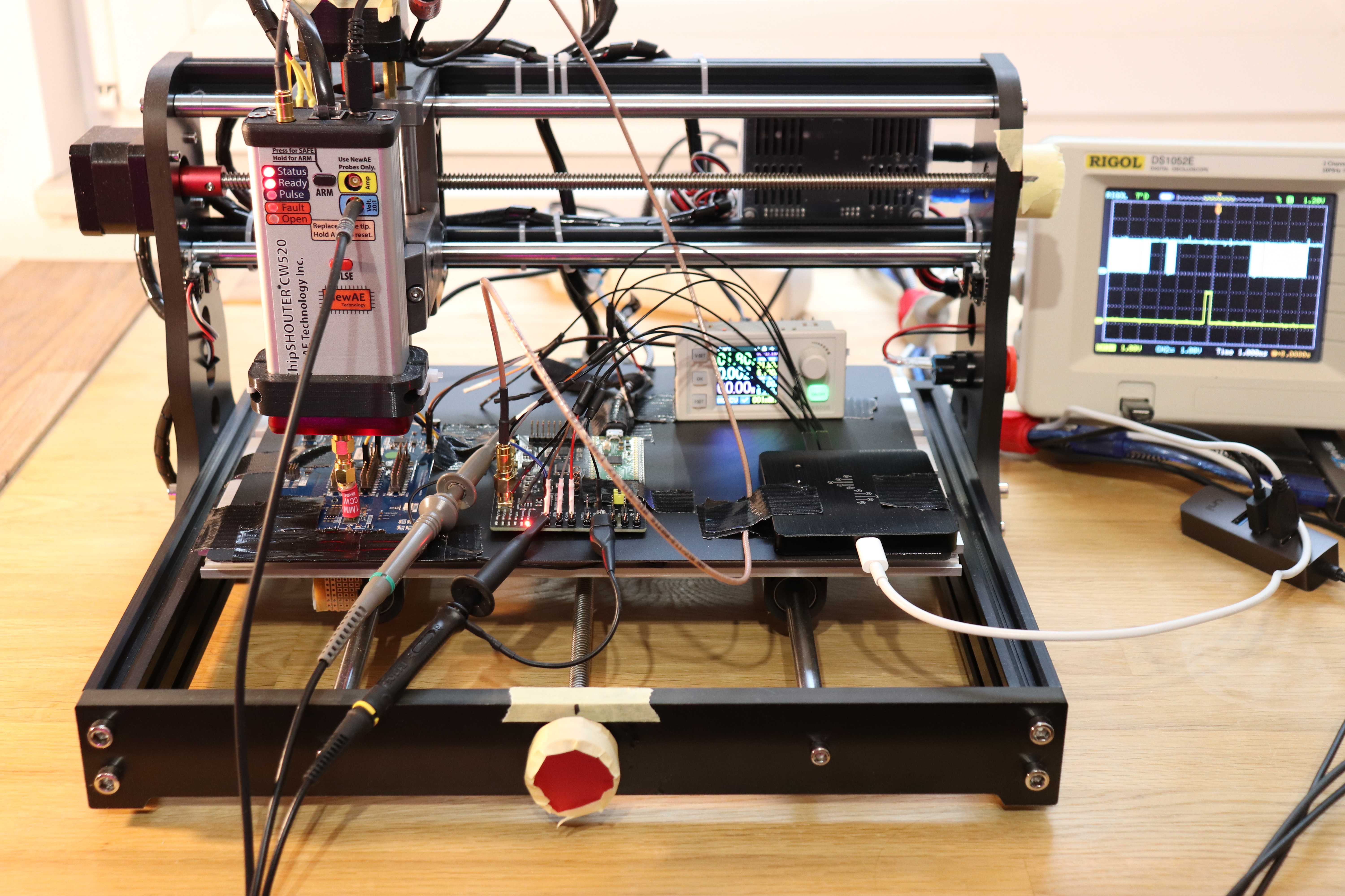 Test setup
All devices and components are secured to the CNC table with duct tape. It is important that the target device is secure and does not move during the experiments. To easily find the initial probe position, painter’s tape is used to mark the x-, y- and z-positions of the CNC table.
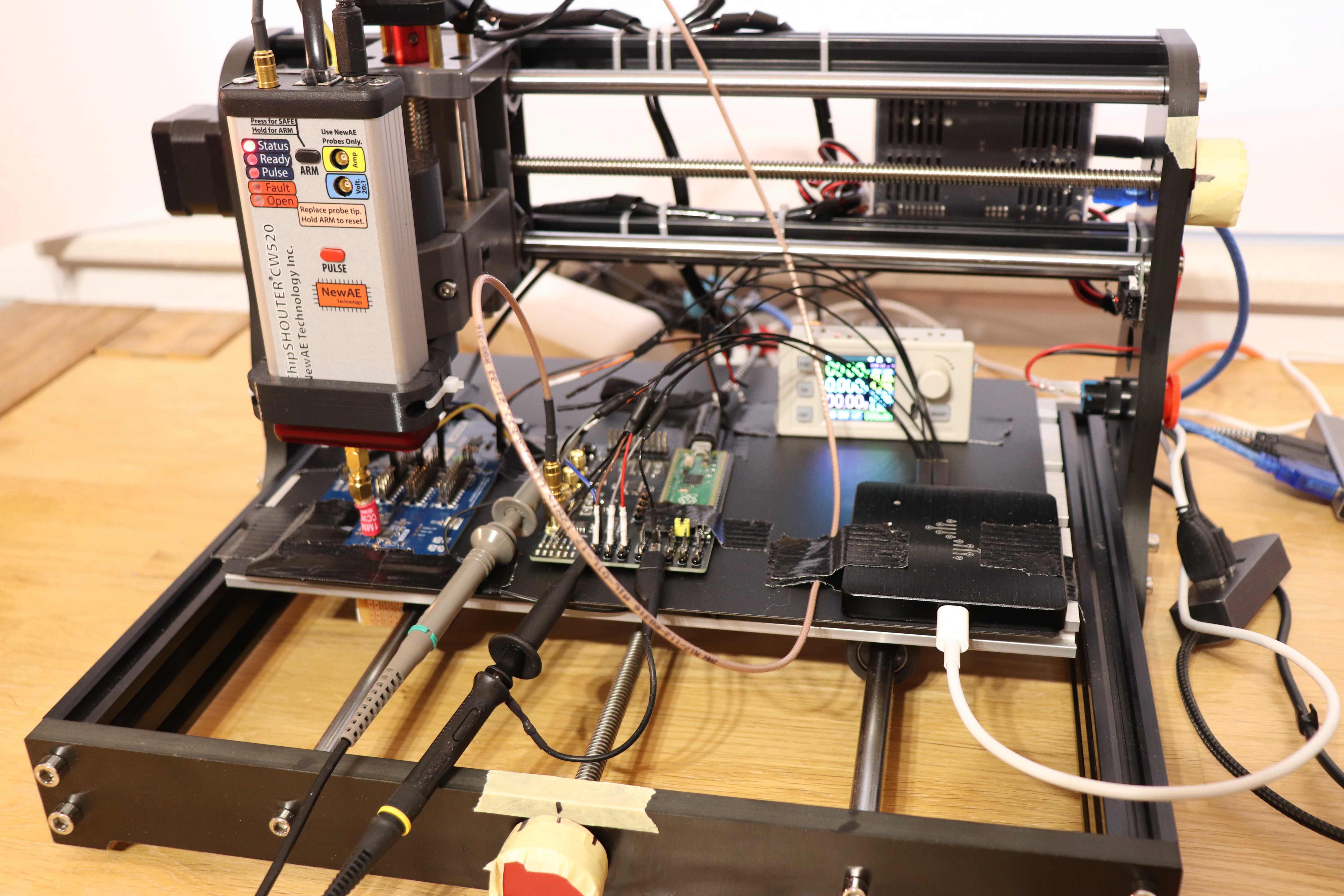 CNC table to move the EMFI probe
Tests were performed using different coils. However, the 1 mm CCW probe produced the best results. The picture below shows a close-up of the target under test and the ChipSHOUTER coil.
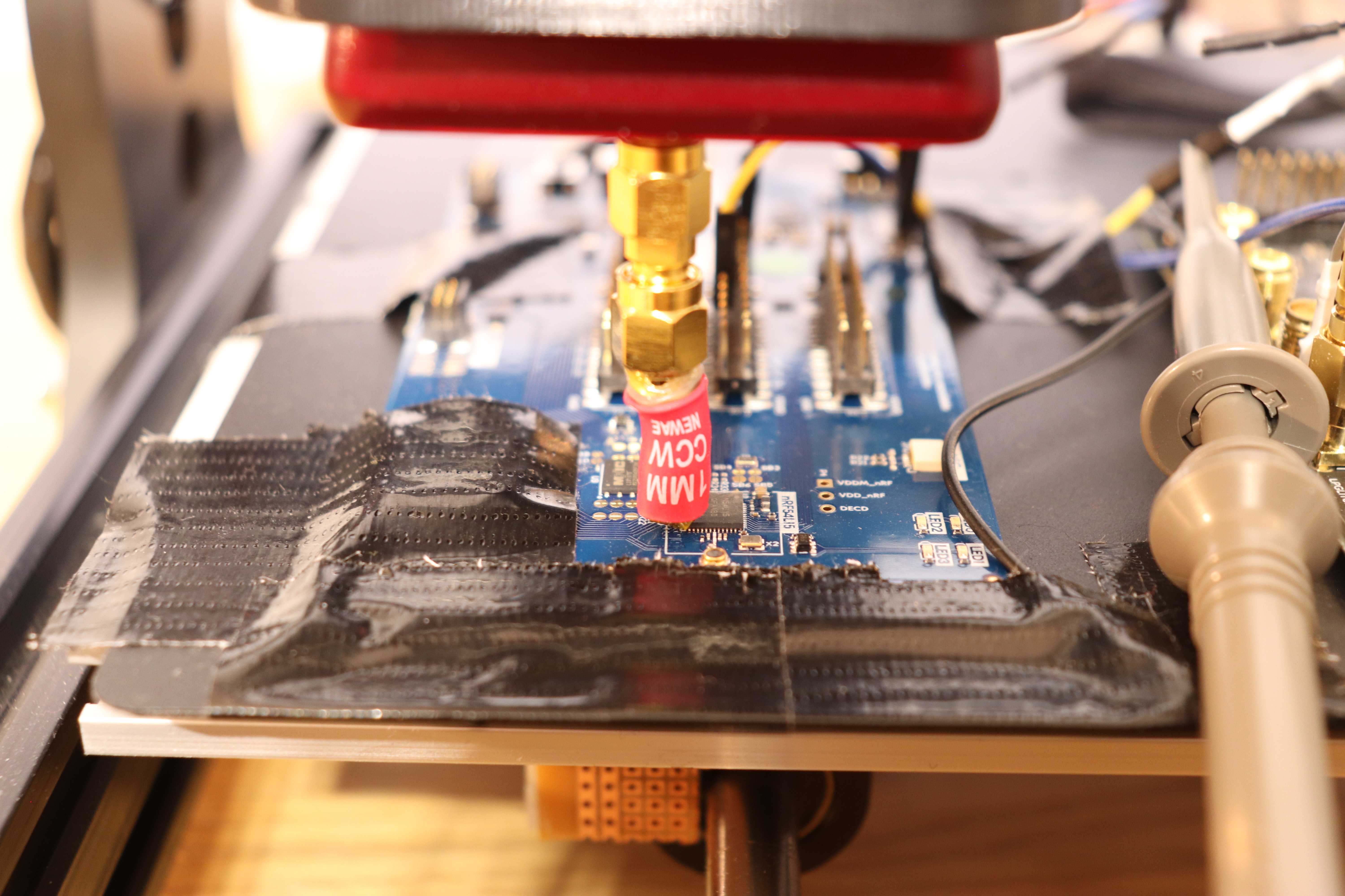 nRF54L15 target under test
Pico Glitcher, findus and emfindus
As in previous tests, the Pico Glitcher plays a key role in the setup. It is configured to trigger when a rising-edge signal is received from the target device. The Pico Glitcher also controls both the target’s power and the reset signal.
Scripting is carried out using the fault injection library (a.k.a findus). This software is used to configure and control the Pico Glitcher, and to characterize and store experiments in a database. The fault injection library provides useful functions for handling all the complex processes. The “analyzer” tool of findus can be used to display events in a web application and to provide an overview of the parameter space.
A second library, emfindus, was developed to enable communication between the CNC table, the ChipSHOUTER and the host computer.
Glitching script
The glitching script begins with the configuration of all devices, the setup of the database, and the enabling of device communication.
1
2
3
4
5
6
7
8
9
10
11
12
13
14
15
16
17
18
19
20
21
22
23
24
25
26
27
28
29
from findus import Database, PicoGlitcher, Serial, Helper, ErrorHandling
from emfindus import ChipShouterInterface, MachineController
...

class Main:
    def __init__(self, args):
        # Pico Glitcher for resetting and power-cycling the target
        self.pico = PicoGlitcher()
        self.pico.init(port=args.rpico, ext_power=args.power, ext_power_voltage=1.8)
        self.pico.rising_edge_trigger(pin_trigger=args.trigger_input)
        self.pico.set_lpglitch()

        # set up the database
        self.database = Database(sys.argv, resume=self.args.resume, nostore=self.args.no_store, column_names=["voltage", "length", "delay", "x", "y", "z"])
        self.start_time = int(time.time())

        # interface to ChipSHOUTER
        self.shouter = ChipShouterInterface(port_chipshouter=args.shouter, external_trigger=args.external_trigger)

        # interface to CNC table
        self.cnc = MachineController(port=args.cnc, limits=False, max_x=0, max_y=0, max_z=0)

        # Serial connection to the target
        self.serial = Serial(port=args.target, timeout=0.01)

        # error handling
        self.error_handler = ErrorHandling(max_fails=args.number_of_tries*5, look_back=args.number_of_tries*5, database=self.database)

    ...
Next, a connection to the CNC table is established and it is moved to the starting position. The experiment parameters are then loaded.
1
2
3
4
5
6
7
8
9
10
11
12
13
14
15
16
17
18
19
20
21
22
23
24
25
26
27
    def run(self):
        # move the CNC table to the correct position
        self.cnc.connect()
        self.cnc.setup_position(homing=self.args.homing, manual_positioning=self.args.manual_positioning, go_to_last_working_position=self.args.last_working_position)

        # get the parameters
        s_voltage = self.args.voltage[0]
        e_voltage = self.args.voltage[1]
        d_voltage = self.args.voltage[2]
        s_length = self.args.length[0]
        e_length = self.args.length[1]
        d_length = self.args.length[2]
        s_delay = self.args.delay[0]
        e_delay = self.args.delay[1]
        d_delay = self.args.delay[2]
        s_x = self.args.scanx[0]
        e_x = self.args.scanx[1]
        d_x = self.args.scanx[2]
        s_y = self.args.scany[0]
        e_y = self.args.scany[1]
        d_y = self.args.scany[2]
        s_z = self.args.scanz[0]
        e_z = self.args.scanz[1]
        d_z = self.args.scanz[2]

        # bring the target to a known state
        self.pico.reset()
The next step involves selecting a random parameter point (CNC table position, coil voltage, length and delay of the pulse) and moving the ChipSHOUTER probe to the chosen position. The ChipSHOUTER device is initialized and the Pico Glitcher is armed. The electromagnetic pulse is emitted with a delay after the trigger condition is observed, i.e. after a rising edge is detected by the Pico Glitcher on a target’s GPIO pin.
1
2
3
4
5
6
7
8
9
10
11
12
13
14
15
16
17
18
19
20
21
22
23
24
25
26
27
28
29
30
31
32
33
34
        # start experiments
        experiment_id = 0
        while True:
            # move table to random position
            x = Helper.random_point(s_x, e_x, d_x, dtype=float)
            y = Helper.random_point(s_y, e_y, d_y, dtype=float)
            z = Helper.random_point(s_z, e_z, d_z, dtype=float)
            self.cnc.move_abs_xyz(x, y, z, f=300, safety_mode=False)

            # check every point multiple times with random parameters
            for _ in range(0, self.args.number_of_tries):
                voltage = Helper.random_point(s_voltage, e_voltage, d_voltage, dtype=int)
                length = Helper.random_point(s_length, e_length, d_length, dtype=int)
                delay = Helper.random_point(s_delay, e_delay, d_delay, dtype=int)

                # initialize the ChipShouter
                self.shouter.init(voltage=voltage, pulse_width=length)

                # check if shouter is available or if there are faults
                self.shouter.block()

                # arm the Pico Glitcher
                self.pico.arm(delay, length)

                # reset target
                time.sleep(0.01)
                self.pico.reset(0.01)

                # block until triggered
                try:
                    self.pico.block(timeout=1)
                except Exception as _:
                    print("[-] Timeout received in block(). Continuing.")
                    self.pico.power_cycle_target()
Finally, the response of the device is captured and categorized. The outcome of the experiment is stored in a database.
1
2
3
4
5
6
7
8
9
10
11
12
13
14
15
16
                # check response
                garbage = self.serial.read_until(expected=b'*** Booting nRF Connect SDK v2.9.0-7787b2649840 ***\r\n')
                garbage = self.serial.read_until(expected=b'*** Using Zephyr OS v3.7.99-1f8f3dc29142 ***\r\n')

                response = self.serial.read(53)
                self.serial.flush_v2(timeout=0.5)

                # classify response
                color = self.shouter.classify_glitchdet_enabled(response)
                #color = self.shouter.classify_glitchdet_disabled(response)

                # add to database
                response_str = str(response).encode('utf-8')
                self.database.insert(experiment_id, voltage, length, delay, x, y, z, color, response_str)

                ...
The script is executed with the following arguments:
1
2
3
4
python nrf54l15.py --rpico /dev/ttyACM0 --target /dev/ttyACM2 --cnc /dev/ttyUSB1 \
         --shouter /dev/ttyUSB0 --length 90 110 1 --delay 0 310_000 1 \
         --voltage 190 190 0 -x 0 6 0.1 -y 0 6 0.1 -z 0.1 0.4 0.1 \
         --number-of-tries 5 --external-trigger --homing --last-working-position
With these parameters a electromagnetic pulse with a duration between 90 and 110 ns after a delay between 0 and 310,000 ns is generated.
The coil is charged with 190 V.
The CNC table is instructed to cover an area of 6 mm x 6 mm and a z-height between 0.1 and 0.4 mm.
Varying the distance (z-height) of the coil from the target device effectively controls the strength of the electromagnetic field.
Furthermore, the area affected by the electromagnetic pulse is influenced by the distance of the probe from the target.
It was found that adjusting the z-height was more effective than adjusting the coil voltage.
The --number-of-tries argument controls the number of attempts made at each position before moving on.
To resume from the last position after restarting the script, the CNC table is homed using the --homing argument and moved to the last working position using the --last-working-position argument.
Results
Test runs are performed with and without the glitch detector activated to observe its effects. The following two figures demonstrate the significant impact of enabling the glitch detector on the outcome of the experiments. The green dots represent events where nothing happens and the outcome of the calculation is as expected. Events marked in yellow or magenta are of interest to the attacker since they indicate that the microcontroller has reacted to the fault injection. Red and orange dots indicate experiments in which the fault injection modified the checksum calculation (successful or “positive” events).
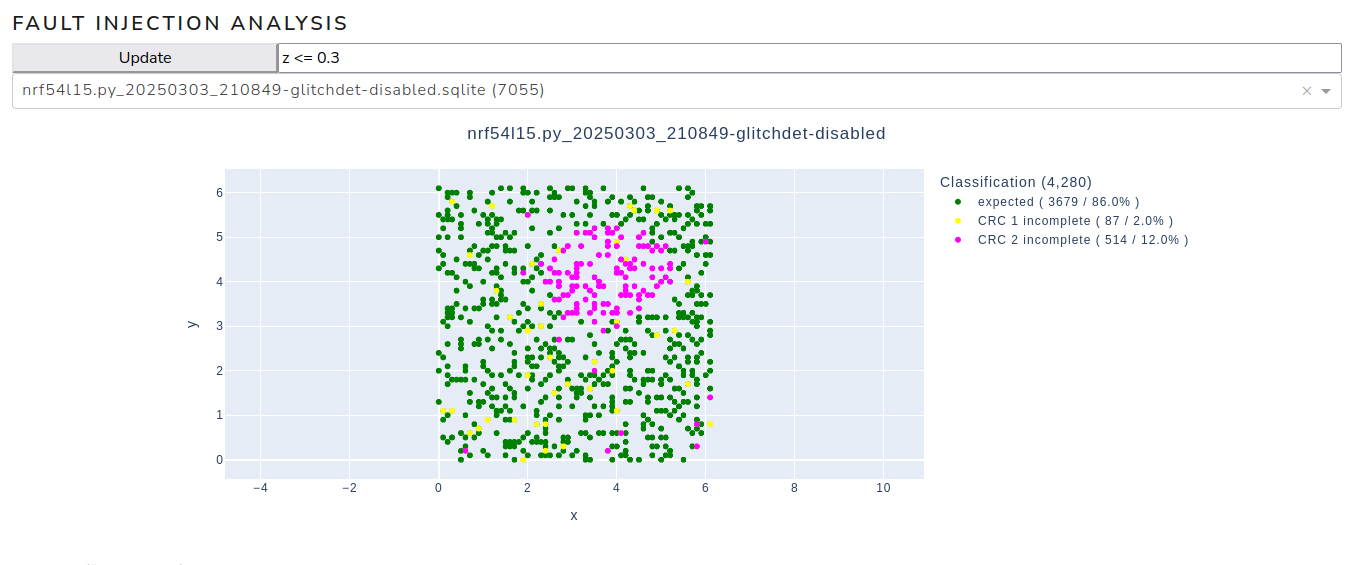 Parameter space with glitch detector disabled
A second island of magenta events, where the microcontroller is shut down by the glitch detector, becomes visible when the glitch detector is activated, as can be seen in the following figure.
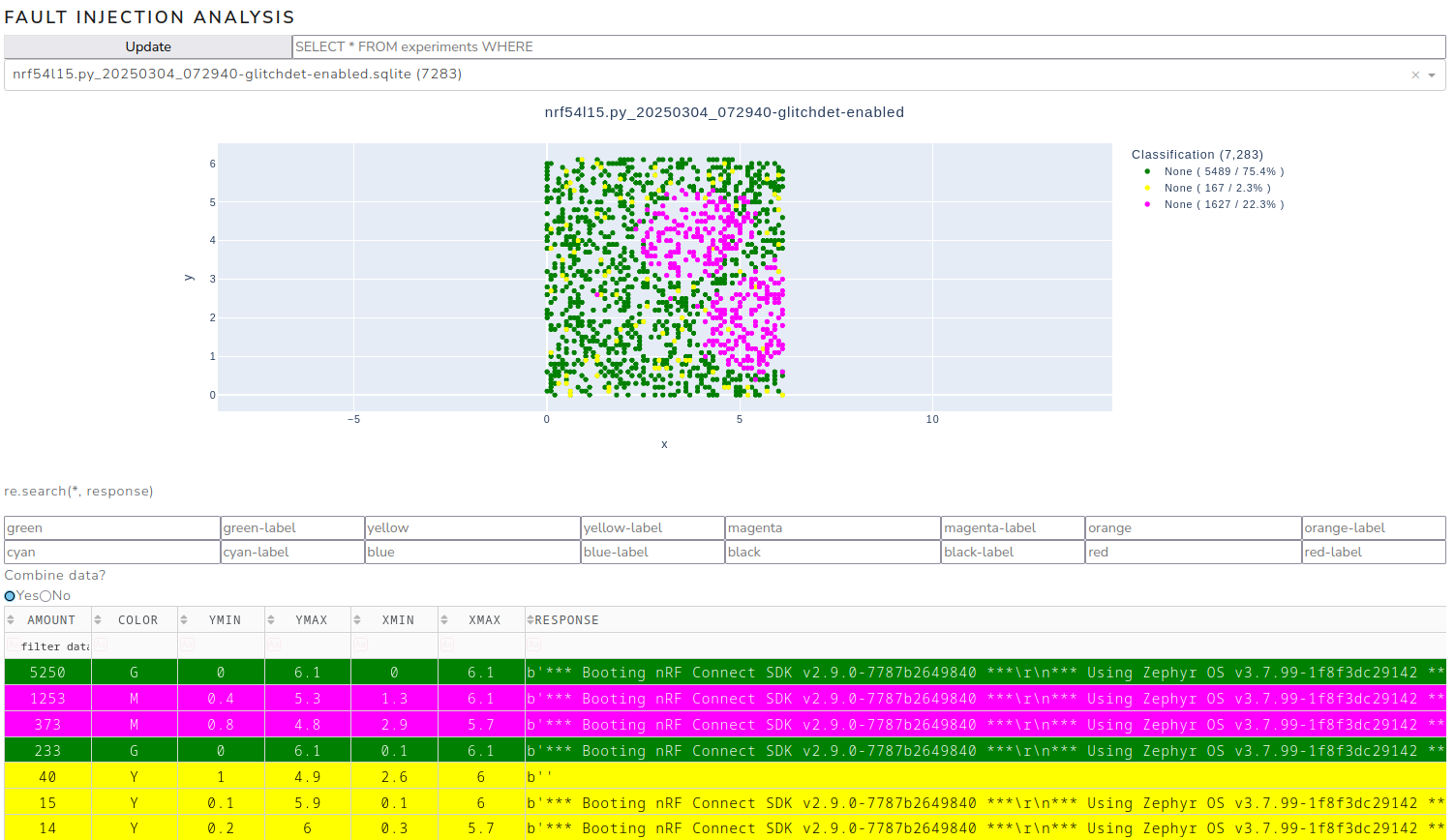 Parameter space with glitch detector enabled
As the upper island is visible in both cases, subsequent experiments will focus on this area. Positive events are expected to be found here. Indeed, closer examination of the upper island revealed positive outcomes at the transition between the magenta island and the expected results.
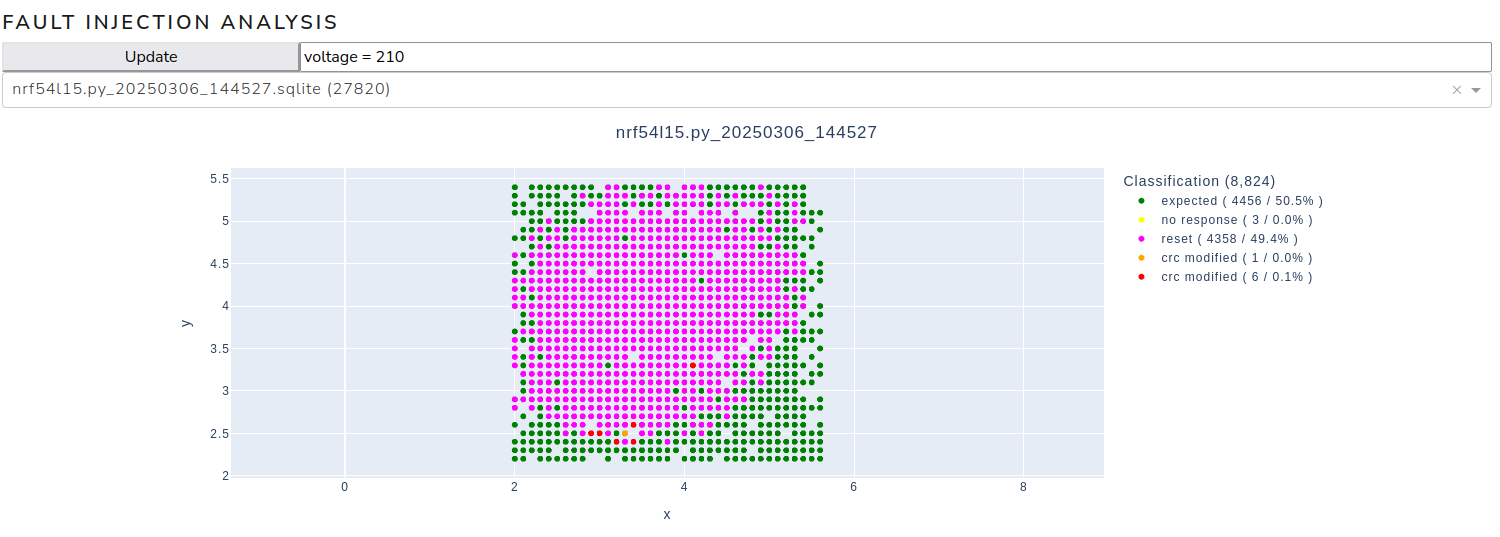 Positive events
To further improve the success rate, a detailed scan of the lower part of the island is carried out. Scanning this area achieved a success rate of 2.4%.
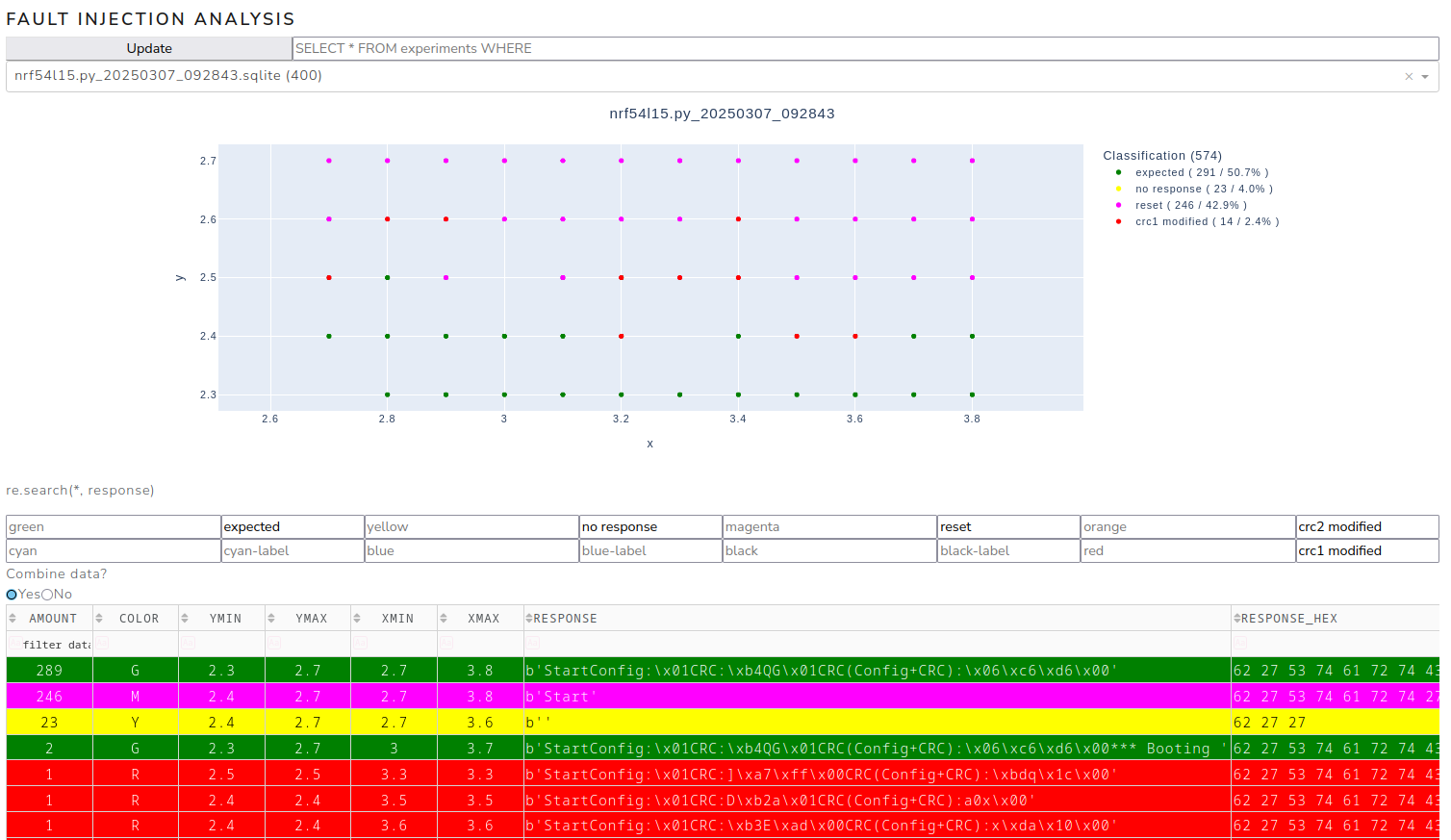 Positive events
Conclusion
Even though only a proof of concept of a checksum modification has been shown so far, this work makes it clear that even hardware with a dedicated glitch detector can be attacked via EMFI. It also shows that despite great efforts to secure the hardware against fault injection, there is always a residual risk. Future work will investigate whether this attack is suitable for circumventing the microcontroller’s readout protection.
Details of this vulnerability have also been published in the advisory SYSS-2025-022.